Tuning fork choppers are the most reliable choppers. They have an infinite lifetime. They can work in high temperature, ultra high vacuum and cryogenic environments. Tuning fork choppers are used for chopping light, plasma, X-ray and laser light.
They are low cost - especially in larger quantities, compact size, lightweight and have virtually unlimited life. This make the tuning fork choppers suitable for dedicated applications, OEM, built into an instrument or system, and for small, portable and hand-held systems. Tuning fork chopper that meets MILITARY SPECIFICATIONS are available as a special order.
A tuning fork chopper is a ONE FIXED FREQUENCY electromechanically driven light chopper. Vanes, attached to moving tines, modulate a light beam. The chopper operates at the natural resonant frequency established by the effective mass of the moving assembly and the spring constant of the tines.
The one FIXED chopping frequency is chosen from a range (see table below). Apertures up to 15mm are practical in the lower frequencies (under 100 Hz). If the beam size is limiting the chopper frequency, consider focusing the beam.
The motion amplitude of the chopper is inversely proportional to its frequency. You can find examples of the frequency amplitude relationship in the table below. Dark or bright vanes are standard; mirrors, lenses or gratings are optional. The standard operating temperature is -40 deg C to +65 deg C.
Balanced operation and high "Q" insure excellent frequency stability, low electrical drive power and low reaction forces. High flexural stiffness provides good resistance to shock and vibration. Tuning fork choppers are cryogenic and high temperature capable. They can be constructed of low out-gassing materials for ultra high vacuum. A significant use of tuning fork choppers is in aerospace and atmospheric research. Tuning fork choppers take part in distinguished space research projects around the globe. Another important use of the tuning fork chopper is in detection applications, where optical signals are obscured by noise. A fixed frequency modulated signal can be filtered from background noise. This is best achieved using a lock-in amplifier. The detected signal and the reference signal (mixed with the frequency of the tuning fork chopper) cause the frequency of interest to appear as a pure dc output level. All other signals are filtered with the low pass filter. Once noise is removed, proper signal measurements can be obtained. Tuning fork choppers are used in industrial, aerospace and military applications worldwide.
The ED driver and the AGC driver are both tuning fork oscillators using the chopper as a frequency source. The AGC driver also provides a high amplitude stability (0.005%) and both sine wave and TTL reference signals.
The PLD-1C driver phase locks a tuning fork chopper to an external clock signal.
The PLD-2C driver phase locks two tuning fork choppers in a "master/slave" chopping system.
Special vane configurations, modulating waveforms and shapes are available as a special order (consult EOPC). Drive electronics with different package, regulation and power supply options are available. Special pricing is also available for OEM applications.

NOTES
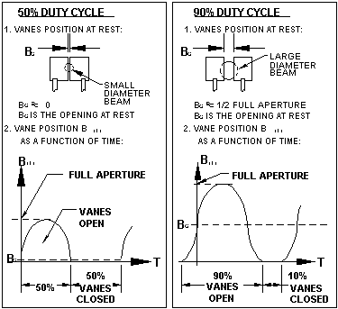
1) For 50% DUTY CYCLE: The opening at rest is zero.
2) The standard base holds a single coil. A base with two coils is recommended for low frequencies
and high amplitude stability (with the AGC driver). For a wide temperature range, a base with three coils is recommended for high frequencies and high amplitude stability (with the AGC driver).
3) The vane motion is sinusiodal.
CH-20 Optical Modulator:
ONE FIXED FREQUENCY from the range of 200Hz to 6kHz
For 50% duty cycle, the opening at rest is zero.
The vane motion is sinusoidal.
Standard operating temp.: -40°C to +65°C.
The following should serve as guide lines only:
FREQUENCY
(Hz) |
CHOPPER |
BASE |
OPENING
(Inches) AT REST |
|||
A |
B |
C |
D |
E |
||
LENGTH
(Inches) |
WIDTH
(Inches) |
HEIGHT
(Inches) |
LENGTH
(Inches) |
WIDTH
(Inches) |
||
200-400 |
1.70 |
0.68 |
0.35 |
0.78 |
0.625 |
0.10 |
400-800 |
1.40 |
0.68 |
0.35 |
0.78 |
0.625 |
0.06 |
800-1000 |
1.30 |
0.68 |
0.35 |
0.78 |
0.625 |
0.04 |
1000-1200 |
1.62 |
0.68 |
0.30 |
1.13 |
0.625 |
0.03 |
1200-1500 |
1.52 |
0.68 |
0.30 |
1.13 |
0.625 |
0.03 |
1500-1700 |
1.33 |
0.68 |
0.30 |
1.13 |
0.625 |
0.02 |
1700-2000 |
1.25 |
0.68 |
0.30 |
1.13 |
0.625 |
0.02 |
2000-2500 |
1.25 |
0.68 |
0.30 |
1.13 |
0.625 |
0.01 |
2500-3000 |
1.06 |
0.68 |
0.30 |
1.13 |
0.625 |
0.007 |
3000-4000 |
0.96 |
0.68 |
0.30 |
1.13 |
0.625 |
0.006 |


FREQUENCY |
50% DUTY CYCLE |
90% DUTY CYCLE |
||
FULL APERTURE |
FULL APERTURE |
|||
| (Hz) | (mm) | (Inches) | (mm) | (Inches) |
200 |
2.5 |
0.10 |
5.0 |
0.20 |
400 |
1.5 |
0.06 |
3.0 |
0.12 |
800 |
1.0 |
0.04 |
2.0 |
0.08 |
1000 |
0.85 |
0.03 |
1.7 |
0.07 |
1500 |
0.70 |
0.03 |
1.4 |
0.06 |
2000 |
0.40 |
0.02 |
0.80 |
0.03 |
2500 |
0.25 |
0.01 |
0.50 |
0.02 |
3000 |
0.20 |
0.008 |
0.40 |
0.016 |
4000 |
0.18 |
0.007 |
0.38 |
0.015 |
ORDERING INFORMATION
TYPE [CH-20]; DUTY CYCLE [%]; VANE [B=bright or D=dark]; FREQUENCY [Hz]
Example: PART NO. CH20-50D3000. This part number specifies the model CH-20 chopper, with 50% duty cycle, dark vanes and a 3kHz operating frequency.
Special vane configurations, modulating waveforms and shapes are available on special order. Consult factory. Drive electronics with different packages, regulation, and reference signal and power supply options are available. Special pricing for OEM applications.