
Resonant scanners are used for both projection and data acquisition applications.
The SC-30 model high speed resonant scanners are good candidates for the high frequency "X" scanner in X,Y raster scanning systems and for systems locked in a master/slave mode.
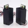
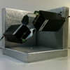
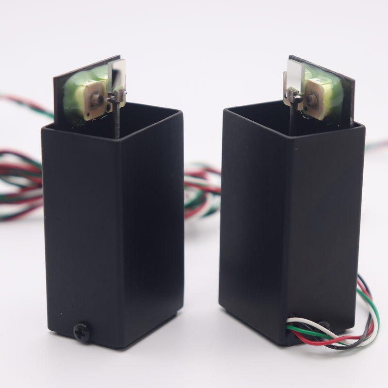
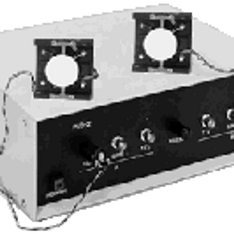
The SC-SYS-2SXY scanning system is generated by two resonant scanners of different frequencies (type SC, except for the subminiature scanners) locked in a MASTER/SLAVE mode. Scanner "X" is high frequency and scanner "Y" is low frequency. The two scanners are ONE FIXED FREQUENCY each, picked from the range of 5 Hz to 20 KHz. They are small size, light weight, low cost and long life devices. They require low power drive electronics and do not radiate any electromagnetic interference (EMI). The scanners have high amplitude stability and very low amplitude jitters; wobble is less than 1 arc sec. The scanners are IR, VIS, UV and high vacuum capable.
Scanner "X" is operating at its resonant frequency Fx. The ratio of the frequency of scanner "X" to the frequency of scanner "Y" (Fy) is "n". Thus, n = Fx/Fy, where n is a whole number and is factory set to customer requirements.
The PLD-2SXY driver is fully integrated with front panels controls and internal power supplies. The PLD-2SXY-PC driver is a printed circuit board level driver, which requires an external ±15V DC power supply.
PLD-2SXY driver locks two resonant scanners (type SC, except for the subminiature scanners) each of a different frequency in a MASTER/SLAVE phase locked mode to generate a repetitive pattern (e.g.: a raster scan or Lissajous patterns).
An X,Y raster scan system can be generated by locking two resonant scanners in a master/slave mode.
The system consists of scanner "X" (high frequency) and scanner "Y" (low frequency). The two scanners are ONE FIXED FREQUENCY each, picked from the range of 10 Hz to 16 KHz (e.g.: 10 KHz).
Scanner "X" is operating at its resonant frequency (Fx).
Scanner "Y" is phase locked to scanner "X" in a MASTER/SLAVE mode. The phase relationship to the master scanner is set by the factory to customer's requirements (0° to 360°) and is front panel adjustable in the range of +/-45° min.
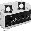
The PLD-2SXY-110 or PLD-2SXY-220 driver is a fully integrated boxed driver for 110V or 220V (please specify). The driver has front panel controls for amplitude and phase and internal power supplies. The dimensions of the cased driver are: 12 X 10 X 3.8".
The PLD-2SXY-110/220 is a version of the boxed driver with a line switch selector for operating from a line voltage of 110Vac or 220Vac.
The PLD-2SXY-PC driver is a printed circuit board level driver which requires an external +/-15V DC power supply.
The system can be used as a "stand alone" unit or can be incorporated into an instrument or a system. Although the scanners can be used in a large temperature range this driver is not recommended for use in temperature sensitive applications.
FRONT PANEL CONTROLS
| POWER | Power switch to turn the drive "ON" |
| LOCKED MODE | The scanners are phase locked in a master/slave mode |
| OSCILLATOR MODE | The scanners are self oscillating at their resonant frequency (not locked) |
| PHASE CONTROL POT | Phase adjustment of the scanners in relationship to each other, +/- 45 |
| POSITION MONITOR | Scanner position output each scanner, BNC connector |
| AMPLITUDE CONTROL | Scan amplitude adjustment POT for each scanner |
| OUTPUT | Output connector to interconnect to each scanner |
SPECIFICATIONS
| Frequency range | 10 Hz to 16 KHz |
| Scanner amplitude stability | 0.01% or better |
| Position monitor | Analog position output, +/-5V max. 1k ohm max load |
| Scanner amplitude stability | 0.01% or better |
| Phase adjustment range | +/-45° min. |
| Phase stability | 0.01% |
| Frequency ratio Fx/Fy | Factory set to customer specifications |
| Operating temperature range | Room temperature only |
| Power input | 110V ac or 220V ac, 50-60 Hz, 20W |
APPLICATIONS
The system can be used as a "stand alone" unit, in the laboratory, or can be incorporated into an instrument or a system. X,Y scanning systems provide inexpensive high performance for limitless applications involving beam deflection: TV, HDTV, for 2D and 3D imaging, lithography, photo typesetting, for color separation, CAD/CAM, high resolution display systems, web inspection and for laser marking systems to name a few. The scanning systems are also used for robotics, medical non-invasive research and testing, transportation, non-impact printing and laser scanning, inspection systems and high speed, high resolution display system and machine vision. Many applications are in the IR & UV wavelength, high vacuum or cryogenic conditions. The scanner withstands shock and vibration, it can be mounted on moving vehicles, moving arms of an inspection system or a robot.
The 16 KHz and the 8 KHz scanners are most suitable to meet the line scan high resolution requirements for TV/HDTV. However, the 8 kHZ scanner with simultaneous bi-directional scanning will produce the same scan line per frame (page) rate with the same pixel placement accuracy. Operating at the frequency of 16 KHz, 8 KHz and 4 KHz eliminates external vibrations. Resonant scanners offer very low cross axis wobble. Scan-to-scan repeatability is well below 1 arc sec PTP optical.
To achieve high resonance frequency, it is important to keep the inertia as low as possible. It is recommended that the user will choose a beryllium mirror for frequencies of 8 KHz and above. This mirror provides high stiffness and low inertia.
Electro-Optical Products Corp. can supply the complete two axis resonant scanner-galvanometer (polygon) scanning system, or the resonant scanners with drive electronics needed for the customer to build the system.
X,Y scanning systems provide inexpensive high performance for applications involving beam deflection: TV, HDTV, for 2D and 3D scanned objects, for color separation, to generate images stored in computer memory and project them onto a screen, to generate data and/or transfer data directly to production units (CAD/CAM) and for inspection systems to name a few. The scanning systems are used for robotics, medical non-invasive research and testing, transportation, non-impact printing and laser scanning, inspection systems and high speed, high resolution display system and machine vision.
ORDERING INFORMATION
A) SCANNER INFORMATION:
TYPE [SC-XX]; MIRROR SIZE [mm]; ANGLE [P-P Deg. optical]; FREQUENCY [Hz]
Example: PART NO. SC-10-10×10-20-100. This part number specifies the model SC-10 scanner, a 10mm square mirror, a 20° peak to peak optical scan angle and a 100 Hz operating frequency.
B) DRIVER INFORMATION:
Per customer's specifications