The SC-SYS-1S scanning system locks a resonant scanner to an external clock.
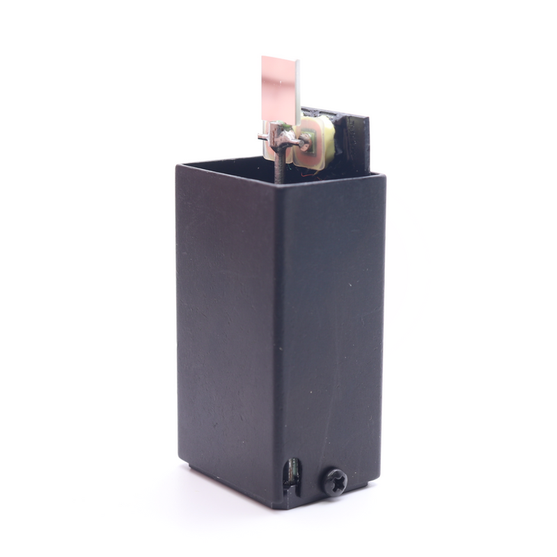
The PLD-1S driver phase locks any resonant scanner (type SC, except for the subminiature scanners) to an external clock signal, to provide an ultra stable scanning beam motion [sub] system. The system can be used as a "stand alone" unit, in the laboratory, or can be incorporated into a larger instrument/system. The scanner is ONE FIXED FREQUENCY, picked from the range of 5 Hz to 20 KHz. The scanner is a small size, light weigh, low cost and long life device. It requires low power drive electronics and does not radiate electromagnetic interference (EMI). The scanner has high amplitude stability and very low amplitude jitters; wobble is less than 1 arc sec. The scanner is IR, VIS and UV and high vacuum capable. Reference signal and position output available.
Although the scanner can be used in a large temperature range this driver is not recommended for use in temperature sensitive applications. To lock the scanner to an external clock signal you need to specify the exact clock frequency (to 4 decimal places). The phase relationship to the clock is factory set to customer's requirements (0° to 360°).
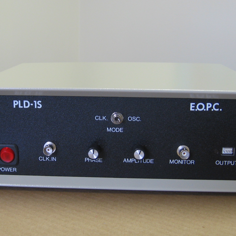
The PLD-1S-110 or PLD-1S-220 driver is a boxed driver for 110V or 220V (please specify). The driver has front panel controls for amplitude and phase and internal power supplies. The dimensions of the cased driver are: 12" × 10" × 3.8"
The PLD-1S-110/220 is a boxed driver with a line switch selector for operating from a line voltage of 110Vac or 220Vac.
The PLD-1S-PC driver is a printed circuit board level driver which requires an external +/-15V DC power supply.
The phase relationship to the clock is factory set to customer's requirements (0° to 360°), and is front panel adjustable in a range of ±45 ° min. The driver can be a fully integrated driver with front panels controls and internal power supplies or a printed circuit board level driver. The dimensions of the cased driver are: 12" × 10" × 3.8". The PLD-1S-PC driver is a printed circuit board level driver which requires an external ±15V DC power supply.
CLOCK REQUIREMENTS
| EXTERNAL CLOCK STABILITY | +/-50 PPM |
| EXTERNAL CLOCK ACCURACY | 100 PPM |
FRONT PANEL CONTROLS
| POWER | Power switch to turn the drive "ON" |
| CLOCK IN(PUT) | External clock input (TTL or sine wave), BNC connector |
| LOCKED MODE | The scanner is phase locked to the clock signal |
| OSCILLATOR MODE | The scanner is self oscillating at its resonant frequency (not locked to the clock input |
| PHASE CONTROL POT | Phase adjustment of the scanner in relationship to the clock, +/-45° min. |
| POSITION MONITOR | Scanner position output, BNC connector |
| AMPLITUDE CONTROL | Scan amplitude adjustment POT |
| OUTPUT | Output connector to interconnect to the scanner |
SPECIFICATIONS
| Frequency range | 5 Hz to 16 KHz |
| External clock signal | TTL level, sine or square wave (1V PTP to 20V PTP) |
| External clock stability | +/-50 PPM |
| Scanner amplitude stability | 0.01% or better (not locked to the clock input) |
| Position monitor | Analog position output, +/-5V max. 1kOhm max load |
| Phase adjustment range | +/-45° min. |
| Phase stability | 0.01% |
| Phase relationship | Factory set to customer specifications |
| Operating temperature range | Room temperature only |
| Power input | 110V ac or 220V ac, 50-60 Hz, 20W |
ORDERING INFORMATION
A) SCANNER INFORMATION:
TYPE [SC-XX]; MIRROR SIZE [mm]; ANGLE [P-P Deg. optical]; FREQUENCY [Hz]
Example: PART NO. SC-10-10×10-20-100. This part number specifies the model SC-10 scanner, a 10mm square mirror, a 20° peak to peak optical scan angle and a 100 Hz operating frequency.
B) DRIVER INFORMATION:
Per customer's specifications